Losmandy G11 Clutch Modification

  One of the things about the G11 that bothered me was the weak clutch performance. After reading several articles in the Losmandy news group, it appears a few people have the same problem. Though the mount seemed to track fine, the major annoyance was if you accidentally bumped into the OTA, even slightly, the tube moved enough to knock the target I was attempting to image off center, or knocked the guide star out of the field. This happened more than once no matter how hard I tried not to touch the OTA in any way.

  I took the mount apart twice to examine the disk for any signs of grease or oil, which there were none. Even re-cleaning the clutch areas proved useless. In order to get semi-tight clamping force I had to tighten the clutch until the clutch couldn't be turned no more because it was bottomed out.

  As a test to see if this excessive tightening was causing any rotation problems, I removed the OTA and weights and tightened the clutch as tight as I had to in order to get decent clamping force, I slowly rotated the RA axis. What I could feel was a very intermitting flat spot, though it couldn't be reproduced in the same area. This pointed to the most likely possibility of one of the thrust bearing needle rollers not turning momentarily from excessive bearing compression load.

Time to increase friction.....

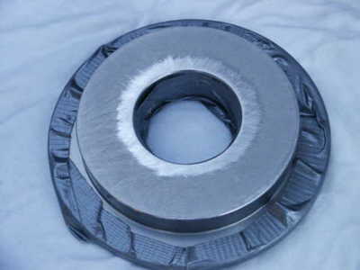
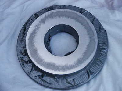
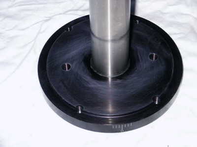
  Getting the clutch surface ready for glass beading in an effort to increase friction without risking dimensional changes, I noticed the inner center portion of the nylon clutch pad to look more compressed when compared to the rest of the surface. I found it hard to believe that much surface area couldn't provide more friction to hold the OTA in place from minor bumps. So out came the straight edge to take a closer look.
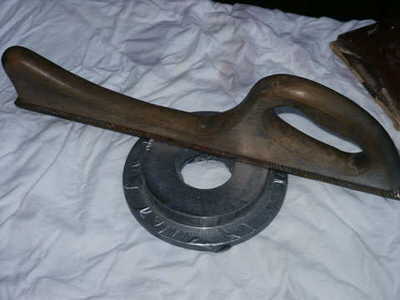
  To my surprise (and disappointment), the straight edge revealed the center hub area to be higher that the rest of the surface. The straight edge didn't even contact the outer edge of the RA clutch surface area when resting squarely on the raised center due to the height difference. 
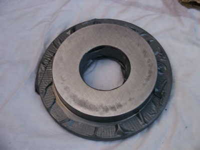
I decided to use my Sheffield steel file that I use for auto body lead work and make a few passes to highlight the high and low areas of the surface. The metal shaved off showed a small ring in the center at first, which indicates the area was raised, which the straight edge showed. After a short while shaving the surface, I decided to stop and take pictures and post the information on the web to share.


This is the raised center highlighted after quite a few passes with the file. Note how the main clutch area is not being touched. This proves only the inner center of the clutch nearest the hub was providing the friction when compressed which explains the weak holding action. This is the Sheffield steel flat file I used attached to a maple wood handle. This is used for lead work on automobile panels and is without question, flat. The most important thing here is to keep the file flat and straight on the raised center when filing so as to mill the section down square. It was important to not stay in one spot or direction. I kept moving around the perimeter of the surface to keep a uniform cut.
After careful milling, the center is now starting to become flush with the outer edge but the center still is low. Notice the duct tape applied to the outer edge of the RA hub to protect the delicate worm grooves and also the inner bearing race. The inner bearing has a dust shield on the race, but I didn't want to risk the remote possibility of getting metal filings into it. Finished milling the surface flat so there is total contact between the inner and outer edges with no cupping. The final stage was to use 600 grit sandpaper and sand in a circular pattern until almost mirror smooth. This is necessary in order to allow the RA axis to freely rotate when releasing the clutch for balancing. The nylon disk will slide along this face when the clutch is released. Clean the surface with a degreaser (I use disk brake cleaner on a paper towel) being careful not to allow any to drip into the bearing area.
This is the anodized surface of the outer RA hub. The surface is smooth and all I did was slightly rough the surface with 600 grit paper though this step may have not been needed. The nylon disk slides on this shaft tightly, so it will not rotate freely when the clutch is released. However this will not prevent the RA axis from freely rotating when the clutch is released as when balancing.


Summary

   After this modification, I only need to turn the clutch 3/4 turn the most from initial contact with the thrust bearing to get a good, solid lock that can withstand minor to firm bumps. This also means there is much less pressure on the bearing. If I tighten the clutch the same amount before the mod, it's very hard to move the OTA on the RA axis. This is a good indication that all of the surface area is being used on the clutch to hold the RA halves together. But why use that much bearing pressure when a little will now do?

  This problem was with my mount, but I suspect more owners G11 mounts have this issue too. Unless you can clearly see a raised center on your hub with a straight edge and you feel you can handle any filing with the proper tools, don't attempt this. Send it back to Losmandy for replacement. I have lots of experience with metal fabrication so I'm comfortable with this sort of work. I also had to repair the digital drive unit that had a piece of metal stuck in the solder between two pins on an IC. This caused the RA motor to drive only in one direction. Who knows, maybe I got the occasional lemon. It was disheartening to spend $2,000 on a mount and have these kind problems with it out of the box. Aside from this annoyance, the Losmandy G11 is still a fantastic bargain for the money when it comes to an imaging platform.


© 2005 Michael A. Siniscalchi