Losmandy G11 One Piece Worm Block

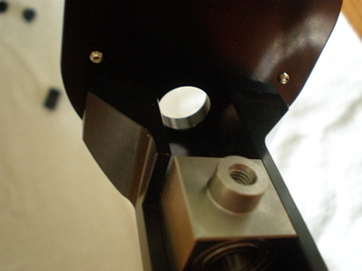
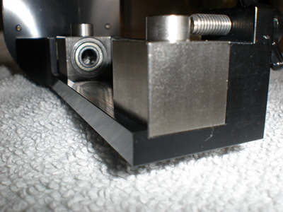
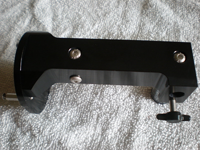
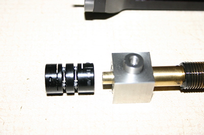
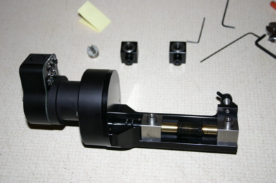
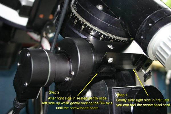
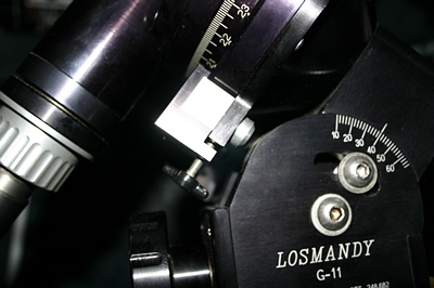
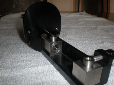
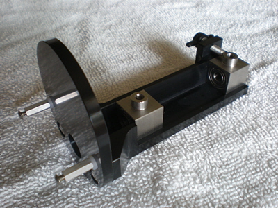
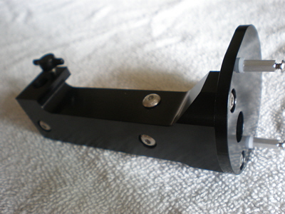
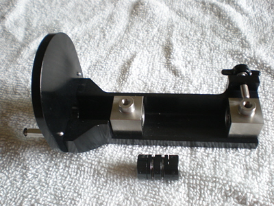
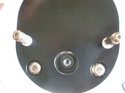
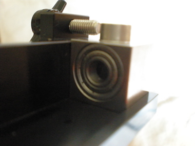
  Below are images and assembly steps of the new Losmandy G11 one piece worm block I received June 11, 2010. This design looks to address the issue of having the worm blocks parallel (supposedly the cause of the 76 second error) and also to make the motor/gear unit part of the worm platform.

>


Assembly Time


  No instructions came with the new piece but it's straight forward. I've added my comments on some parts.

Worm inserted in motor side block and ready to mount the motor coupling union. The Ruland double disc coupler will adjust to minor motor to worm shaft alignment differences (similar to the oldham coupler). This bearing block has 2 bearings so the worm must be inserted square and with care. I used the old bearing blocks with one positioned on the other end of the worm to gently push and the other block in front of the motor side block to push against. Without this support the front bearing in the new block will push out. To keep a small gap between the shaft coupler and the front bearing race I used a piece of folded paper as a feeler gauge and gently pushed the coupler against it before tightening the allen screw on the collar. Otherwise I would recommend .005 to .010" gap if using a metal feeler gauge.
Worm mounted in block. Turning it manually gave a smooth feeling with no signs of binding.
As a side note, after removing the mounting screws I found the blocks fit snug into their positions. Maximum side to side movement along the worm axis between both blocks is approximately .020". fore and aft is 0" (absolutely no play. This shows how precise the machining is.
Click on image for a larger view.
Mounting the motor was straight forward. I found that the screw studs on the motor mounting plate don't use Loctite and would turn trough the mounting plate when screwing on the hex standoffs. I recommend you put your finger nail against the opposite hole so the screw doesn't come out the other side.
  The motor shaft slid effortlessly into the coupler with no jiggling so this shows the centerline of the worm and motor shaft are close in alignment. Once mounted tighten the allen screw on the coupler to lock the motor shaft.
Note: See installation steps below about coupler alignment.
Motor mounted on block. No more motor to worm alignments! Complete block assembly.
Installation - Note the steps to install the block.
Click on image for a larger view
Adjustment - Side view of worm block assembly showing adjustment screw. Keeping the worm assembly held gently against the RA gear, the mounting screws were turned snug. To adjust I slowly turned the adjustment screw until a slight play in gear mesh could be felt while gently rocked the RA axis. Afterwards I tightened the 2 mounting screws.
Worm block and Ruland coupler alignment steps-
  • 1- Carefully slide worm into bearing blocks and place on assembly.
  • 2- Install the coupler on the worm shaft with a .005 to .010" gap between coupler face and bearing then tighten clamp. Align blocks with mounting holes, install screws and turn each screw until it just starts to feel 'seated'. Once all 4 are 'seated' then turn to firmly snug each one. There is no need to over tighten these blocks.

  • Important steps:
  • 3- Insert gear box housing (no drive motor mounted) on studs and insert into coupler end. Install nylon washer and mounting nuts.
  • 4- Turn mounting nuts until it *just* contacts the nylon washers. The object is to let the gearbox move sideways only when centering on the Ruland coupler.
    Optional - If the gearbox body tabs are touching the mounting plate then install a flat washer under each ear to raise body enough so tabs don't touch plate.
  • 5- With thumb gently holding gearbox against the mounting plate turn the coupler clamp just enough to hold worm shaft.
  • 6- Remove thumb from gearbox and while holding the block assembly vertical with the gear box up, rotate coupler a few turns clockwise towards you. This will allow the gearbox to center itself thereby making both shafts parallel (importance of step 4).
  • 7- With thumb gently pressing the gearbox against the mounting plate being careful not to slide box, evenly snug the two mounting studs to secure gearbox. Remember to keep your finger nail against the opposite hole so the studs don't screw through.
  • 8- Loosen the coupler clamp on the gearbox side (you want to maintain the gap on the worm side still) to allow for any residual tension release from securing gear box then retighten.
  • 9- Run the feel test by rolling your finger on the worm gear towards you and feel for any tightness or pulsation during rotation.
  • 10- If necessary loosen the two mounting studs just enough as in step 4 to allow the gear box to slide sideways but not lift up and repeat steps 5 thru 9 until satisfied.
  • Reinstall drive motor. Turn the worm gear to cause drive motor and gearbox gears to engage then snug (don't over tighten) the 2 motor mounting screws and carefully install block on mount head, slightly seat the 2 block mounting screws, adjust 'T' handle to establish a slight play in RA while rocking RA axis. When done firmly snug block screws(see image above). Install RA motor cable and you're ready.

© 2010 Michael A. Siniscalchi